DurAdelta System
A typical durAdelta system will have a Central Control Unit (CCU) and several remote stations providing power and monitoring to the anode zones. The whole durAdelta system has a common RS485 databus communication between each of the modules. One durAdjust system can, in principle have up to 200 power supplies (deltas) and 1,600 reference electrode inputs.
DurAdelta CCU
The durAdelta CCU comprises:
- a CCU cabinet
- a control PLC
- Wireless router or GSM modem for remote control
- a touch screen
- various modules made and designed by CPI
The system controls the current outputs of the anode zones powered from the various remoate stations in compliance with parameters set in the the durAdelta program which can include the data obtained from the sensors in the structure. The output and control data is stored in the CCU on flash memory. Normally there is a modem or a wireless router so these units can be accessed remotely.
DurAdelta Remote Stations
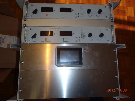
The total system may have several cabinets around the structure containing several types of modules with the assembled delta power supplies each communicating with the central control unit. These cabinets typically contain 8 cards including duraDelta power supply System . The one shown has 2 deltas each of 100A and 24 volts.
Each substation has electronic address and databus isolation .
Remote Control
The durAdelta control system can be remote controlled by modem, with all the functions available on the function buttons and external keyboard also available from the remote control. The remote control can be made from any pc with the right software (NetOp Remote Control Guest) and modem.
The CCU PLC
The system allows you to examine present and historic data concerning the ICCP current and voltage output from the power supplies and potentials from the reference electrodes.
The power supplies can be adjusted manually; voltage (Constant Voltage control) and current (Constant Current control) limits can be set for each of the delta power supplies.
The system can also be setup for potentiostatic control. An internal PID controller is used to adjust current output.
The system constantly checks for errors and reports in case of problems.
Data is logged on a USB memory stíck which is inserted in the front panel adjacent to the control screen. Data is stored as a text file which can be read by Excel or similar spread sheet.
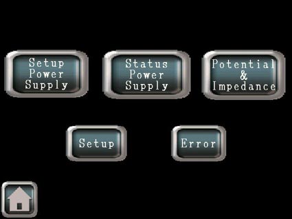
The program is divided into menus which can be chosen from keys on the touch screen. Press here to sess the control screen operations.
DurAdelta Mainscreen
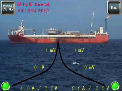
This is a customised durAdelta system which has two zones each of 1,000 Amps at 50 volts to protect this FPSO. The main screen shows a schematic of this FPSO, with two anodes and the instant OFF potentials of the ship measured using the four reference electrodes attached to the anode feeder wires.
The anodes are displayed as LED lamps. The LEDs are green if no problems are found with the power supplies and anodes. In the case of a problem the LED changes to red.
In the upper left corner is a “Remove USB KEY” key. If data is logged on the USB memory key you must press this key to close the data file and thus prevent loss of data by removing the USB key.
The ”Menu” key is placed in the upper right corner.
Menu Items
Setup Power Supply
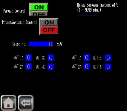
This menu is used to control the power supplies. You can choose between manual controlled output and potentiostatic controlled output. In both cases the maximum output current and maximum output voltage is valid.
The maximum outputs (limits) are entered for each power supplies. They can differ if required.
Press the blue square of the limit you want to change. Numeric keyboards will pop up.
Enter the new value and press OK. The new setting is sent to the power supply.
The delay between instant off is the total single cycle time ( time on and time off).
If you wanted to set it up for 10 minutes on and 1 minute off you would set the instant off delay to 60000 msec and delay between instant off to 11 min.
Use the ON/OFF keys to select Manual Control or Potentiostatic Control.
- When manual control is chosen the OFF key is red.
- When potentiostatic control is chosen the ON key is green
In the case of potentiostatic control the system must know:
- The CP potential (instant off potential in mV)
- Which reference electrodes shall be used to control the power supplies. Some reference electrodes might be closer and thus more important. These are given a higher weight than more remote electrodes.
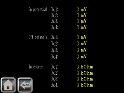
Potential & Impedance
For each of the 4 reference electrodes is measured
- ON potential (mV)
- OFF potential (mV)
- Impedance (kOhm)
Only the OFF potentials are used for potentiostatic control.
The ON potentials can be used for testing positive interference.
The impedance is used to test the reference electrodes. High impedance indicates a failure in the reference electrode (broken cable, passivated zinc etc.).
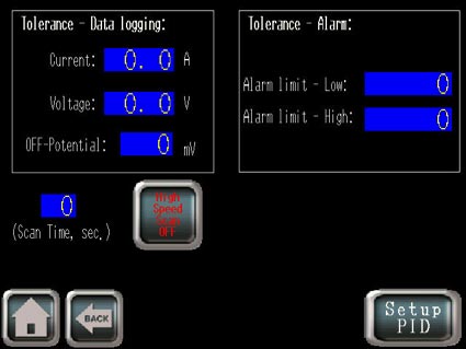
Setup
Data can be logged on a USB memory key.
Data is logged in case of variation of current or voltage; i.e. under normal circumstances the outputs and potentials are very stable and therefore no data will be recorded.
Using the ’High Speed Scan’ key the system can start fast logging of output currents and voltages and ON potentials.
Setup PID
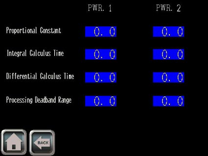
The ’Setup PID’ key in the Setup menu enters the menu for adjusting the PID regulator.
The parameters of the PID regulator are adjusted in the Setup PID menu.
The proportional–integral–derivative controller (PID controller) is a control loop feedback mechanism (controller) widely used in industrial control systems. A PID controller calculates an “error” value as the difference between a measured process variable and a desired setpoint. The controller attempts to minimize the error by adjusting the process control inputs.
The PID controller calculation (algorithm) involves three separate parameters:
- the proportional (P),
- the integral (I)
- and derivative values (D),
In explanation, these values can be interpreted in terms of time: P depends on the present error, I on the accumulation of past errors, and D is a prediction of future error, based on current rate of change. The weighted sum of these three values is used to adjust the process via a control element which is adjusting the current output of the power supplies.
CPI has factory set suitable values for the algorithm for this structure.
Error
If an error occurs the error will be described in the Error menu. The Error menu will automatically pop up. Possible errors that can be seen are: Low current; High current; Low voltage; High voltage; Outside potential range on references; Outside impedance range on references.
Communication
All the durAdelta cabinets are connected through 485 data bus and transmit data at 19,200 baud, 8 bits, even parity, 1 stop bit, half duplex. The RS485 can be run in copper cable (1 twisted pair), fibre optic cable and wireless radio.
The CCU of the durAdelta system is fitted with a HUB allowing 4 branches.
Maximum distance between substations using 1 twisted pair of copper cable is 1100m. The distance can be increased using repeaters. Maximum distance between substations using fibre optics depends of the fibre type and can be up to 25km between RS485 repeaters. Maximum distance using wireless radio depends of the transmitting power, aerials and obstructions between radio modems. Typical range for a radio modem using a free channel in a city area is 1-2km and in flat land 5-10km. Repeaters can be used.
Delta
The delta power units are available in the following sizes:
300 Watts |
max 30 volts 10Amps |
800 Watts |
max 18 volts 50 Amps |
1,500 Watts |
max 15 volts 100 Amps max 35 volts 45 Amps |
3,000 Watts |
max 15 volts 200 Amps max 40 volts 80 Amps max 70 volts 45 Amps |
3,300 Watts |
max 18 volts 220 Amps max 33 volts 110 Amps |
Below are some examples of layout and specifications of some substations used on a bridge with very long cable runs and anodes in the seawater.
Delta Power supply cabinet |
Type 1 |
Cabinet Material |
Coated steel inner frame with stainless outer |
Cabinet Colour |
Beige /sand RAL 1015 |
Door |
Yes hinged |
Internal Swing Frame |
No |
Lock |
Yes, Abloy type |
Operating Power |
Nominal 380-415 V three phase, 48-62Hz |
Communication |
RS485 using one twisted pair wire |
Operating System |
Modbus communications protocol |
AC Terminals |
70 sq mm (each of four) |
Power Supplies |
6 No 70 volt, 45 Amp outputs |
Power Supplies |
4 No 40 volt, 80 Amp outputs |
Power Supply Type |
Switch mode, 200khz MOSFET |
Efficiency |
More than 90% |
Output |
Smoothed 2mv RMS |
Protection |
Can drive in open circuit and short circuit |
Operation |
Either under duracenter or in manual mode |
Mtbf |
More than 500,000 hours |
Thermal Protection |
Progressive internal shutdown |
Inputs |
5 No durahold = 40 No reference electrodes |
Positive Terminals |
10 No 35 sq mm |
Negative Terminals |
20 No 35 sq mm |
Reference Electrode Plus/Ground Terminals |
40 / 40 No 4 sq mm |
Internal Light |
Yes for looking at terminals |
Terminal List |
Yes |
Other Features |
Electrical shock notice |

