DurApower 485 Control System
substations which are the same as the durAdjust monitoing substation except they can also include one or several durApower485 power supply system with a maximum output of 6A at 18 volts. In practice the substation for a durApower485 Control System will contain a durAstore module and are likely to have an appropriate number of durAhold cards for connection of the local half cells. Communications, software and remote control for the durApower485 are the same as the durAdjust485
The DurApower 485 Module
The durApower485 is a power supply that can output 0-24V DC and 0-6A, 144VA. Current output is displayed on the LCD with 1mA resolution and voltage with 10mV resolution. The current and voltage outputs are transmitted to the durAdjust CCU with the same resolution as above.
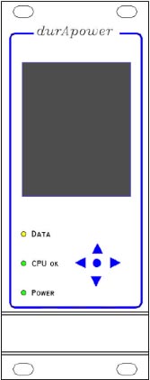
The durApower485 has an OLED screen (176 x 220 pixels) showing measured or setting of voltage and current as well as status information. Under this there are 3 light diodes and 5 press buttons for local manual control of the menus.
Status readouts include:
FAILURE – the voltage is greater than 0.5V and the current is greater than 20mA.
FAILURE LED is on when
1. the output voltage VOUT is greater than 112.5% of setpoint VSET
2. the output current IOUT is greater than 112.5% of setpoint ISET
REMOTE – mode indicates that the durApower is controled by the CCU.
LOCAL – mode indicates that the durApower output is controled by the local settings. The module automaticly change to LOCAL mode if no signal is received within 5 minutes.
CV MODE – indicates that the output voltage has reached the VSET value.
CC MODE – indicates that the output current has reached the ISET value.

The three light diodes of module indicate:
![]() DATA – yellow lights on when there is data transfer to or from the module
DATA – yellow lights on when there is data transfer to or from the module
![]() CPU OK – flashes green once every minute when the internal program is running
CPU OK – flashes green once every minute when the internal program is running
![]() POWER – light is lit when there is power to the logic on in the module
POWER – light is lit when there is power to the logic on in the module
In normal operation the durAdjust control unit will send a signal in order to change to Remote mode. In case of no connection to the control unit the power supply will change to Local after about 5 minutes. (The power supply can also be set in Remote mode by pressing the menu button ) The output in Local mode can be set using menu options. This feature is an extra safety feaute to ensure some degree of cathodic protection in case of communication break down.
The units can cope with, and drive in, either short or open circuit conditions and incorporate automatic temperature sensing where output will shut down in cases of overheating. Temperature is part of the status report of each durApower485.
To provide transient protection the negative returns to the terminals of the durApower485 and common of the durAhold are potentially equalized. (The data bus is galvanically isolated so that other substations can be galvanically isolated from the cabinet.)

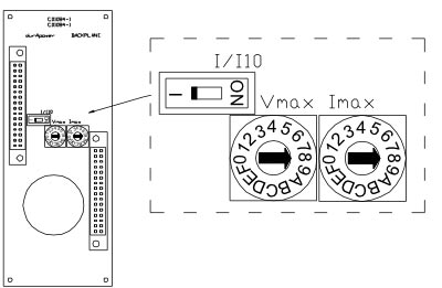
The durApower485 is designed to allow the cathodic protection specialist responsible for commissioning the system to set the maximum voltage and current for each individual output channel. The operators of the system will then only be able to run the system within these set limits. Two 16-pole switches (Imax and Vmax) can respectively be adjusted for maximum current and maximum voltage. The 16-pole switches are placed on the module back plane and are only accessible when the durApower485 module is pulled out of the cabinet, see drawing below. The limits can be adjusted according to the table overleaf. A switch also on the back plane sets the current range: I=0-6A and I/I10=0-600mA.
The DurApower 485 Module
Each durAhold modules has the following features:
- 4 light-emitting diodes. They identify; when the input signal has been logged, when the module is communicating, when the CCU is running, when there is 5V DC to the card. Each inputs has an input amplifier which makes it possible to read an exact instant off potential because each is individually recorded at exactly the same time.
- The input impedance is more than 1Gohm, i.e. at least 100 times higher than a good digital voltmeter. At this very high impedance the reference electrode will not be affected by even exceptionally high resistance circumstances such as being buried in stonework.
- The input capacitance is 10pF which makes the durAhold485 mk3 fast enough to get a more accurate instant off reading, particularly in high resistance environments.
- The instant off measurement time is 20s (cut off frequency = 50,000Hz) and is almost independent of the impedance of the reference electrode as long the impedance of the reference electrode is less than 2 M ohm. The impedance of a normally functioning reference electrode is typically less than 20 K ohm.
- Data sampling is started simultaneously for all half cells.
- On potentials and instant off potentials are read and provided to the durAdjust CCU.
- If the input is noisy the average of two or more readings is used.
- To obtain the very high input impedance and low capacity the durAhold485 mk3 module has a built in auto calibration function. Offset and gain values at 1250mV are read by the durAdjust CCU and each input value is adjusted.
- Due to the very high impedance an input can be read even though there is no source. If a signal has been put on the input the signal will stay for a very long time. Thus it is not possible to check for faulty reference electrodes.
- The durAhold485 mk3 is consequently fitted with impedance measurement of each input. The impedance is measured using a square wave with an amplitude of ±5µA and a frequency of 110Hz. This amplitude is so low and the frequency so high that the electrode cannot be harmed. The impedance measurement is a health check of the reference electrode and is displayed with the instant off reading on the CCU.
- The durAhold485 module just needs to be plugged into the rack. It is automatically addressed when plugged in. Check that the power diode is lit and the CPU is flashing when the system is powered. The durAhold auto calibrates itself against a known internal potential and will display an error if this calibration is deviated from by more than a few millivolts.
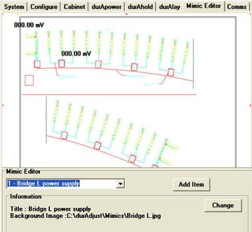
- The durAhold485 has a ‘mimic editor’ function so that schematic pictures of the structure can be installed and reference potentials displayed at representative points (see picture below).


